Cache-Friendly Programming: The Invisible Factor That Determines Performance
So, who here does cache-friendly programming? I'll be honest, I can't do it either.
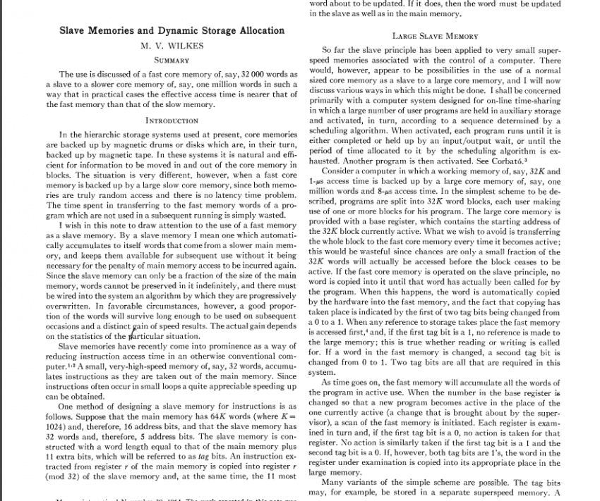
The use is discussed of a fast core memory of, say, 32 000 words as a slave to a slower core memory of, say, one million words in such a way that in practical cases the effective access time is nearer that of the fast memory than that of the slow memory.
— Maurice Wilkes, *Slave Memories and Dynamic Storage Allocation* (1965)
Before we begin...
We are always compelled to write cache-friendly programs.
In modern processors, memory bandwidth and cache efficiency have become core performance factors alongside CPU performance itself.
Even when performing the same operations, performance differences can be extreme depending on how memory is accessed, and understanding and optimizing for this is what cache-optimized programming is all about.
So let's try to understand what a cache actually is.
(Cache Hierarchy)
What Is a Cache?
A cache is high-speed memory designed to bridge the speed gap between the CPU and main memory (RAM).
Every time the CPU needs to process data, going directly to RAM causes a significant performance penalty, so frequently used data is stored in the cache to reduce access time.
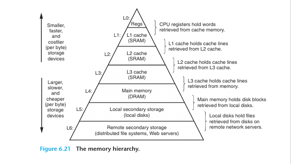
Cache has a hierarchical structure, and modern caches typically have three levels: L1, L2, and L3. (L4 exists in rare cases.)
L1 is the smallest and fastest; as you move toward L3, the size increases but the speed decreases.
So how did this history begin?
History of Cache
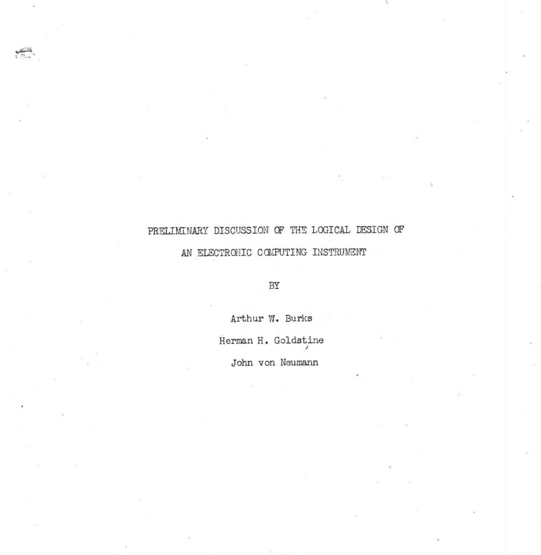
The need for cache memory itself can be traced back to John von Neumann's landmark paper, which played a decisive role in establishing the von Neumann architecture:
"Preliminary Discussion of the Logical Design of an Electronic Computing Instrument" (1946)
as well.
In this paper, the authors recognized the imbalance between the speed of high-speed arithmetic units and memory, and indirectly suggested the need for solutions such as cache memory arising from the limitations of the von Neumann architecture.
The precise origin of cache memory can be found in
Professor Maurice Wilkes's Slave Memories and Dynamic Storage Allocation (1965, Maurice Wilkes).
In this work, cache memory appears under the name Slave Memory.
The term "Slave Memory" implies a hierarchical structure that operates subordinate to main memory, meaning that cache memory functions by copying a portion of the data held in main memory (Core Memory).
(Von Neumann bottleneck image)
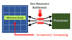
At that time, in the mid-1960s, computer technology was advancing rapidly, yet memory systems suffered severely from the Von Neumann bottleneck.
The reason was that main memory at the time relied primarily on Magnetic Core Memory, which, while stable, had read/write speeds measured in microseconds and could not keep pace with the fast computation speeds of CPUs. This caused overall system performance to degrade.
Accordingly, the Von Neumann bottleneck caused by the difference in data transfer speeds between the CPU and memory was a serious problem.
(Maurice Wilkes)
In this context, Professor Wilkes introduced the concept of Slave Memory in his 1965 paper Slave Memories and Dynamic Storage Allocation.
Slave Memory is the idea of placing a small, high-speed memory layer between the CPU and main memory to increase access speed for frequently used data,
thereby improving overall system performance, and it represents the conceptual prototype of today's cache memory.
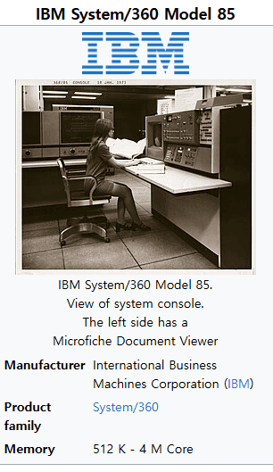
Subsequently, the IBM System/360 Model 85 overcame the technical challenges based on Professor Maurice Wilkes's Slave Memory concept and became the first commercial system to adopt it, after which
the term "cache" was established.
The term "cache" derives from the French word cache (meaning "hiding place"), conveying the idea of memory that keeps frequently used data tucked away for rapid access.
By today's standards the capacity was extremely small, at the kilobyte level, yet it still contributed to improving CPU performance,
and it is regarded as the prototype of the L1 (Level 1) cache memory. At the time, however, only the name "cache" was used; the designation "L1" had not yet been coined.
The L1 and L2 classifications emerged later, as the architecture was reorganized into a multi-level structure.
In any case, L1 cache alone proved insufficient to fully bridge the speed gap between the CPU and main memory, and the need for a larger-capacity cache to supplement L1 began to emerge.
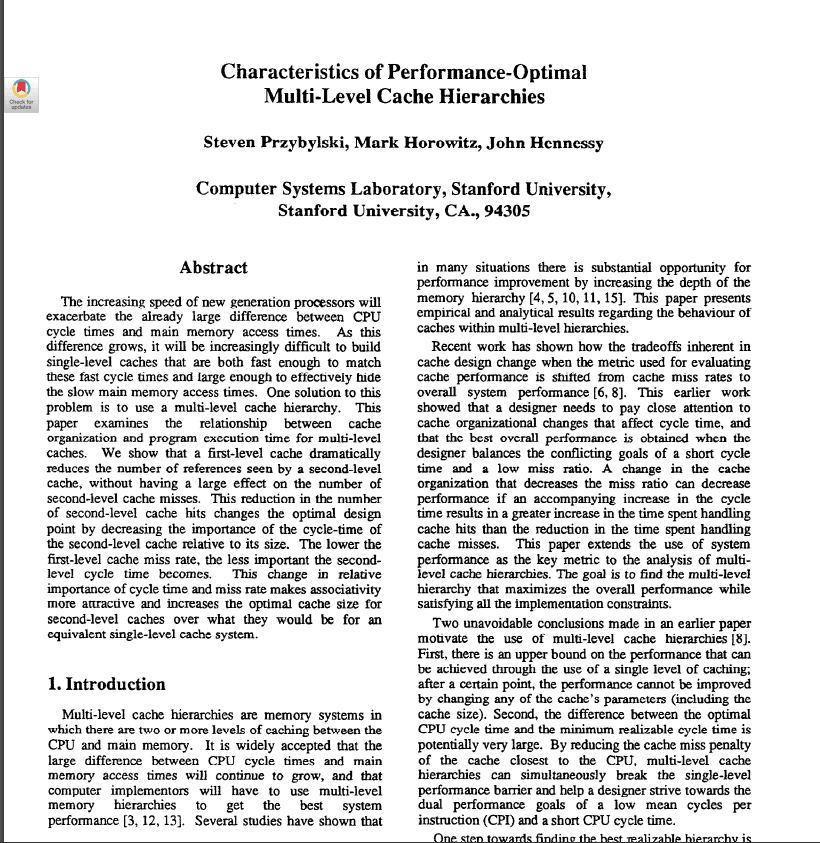
The increasing speed of new generation processors will exacerbate the already large difference between CPU cycle times and main memory access times. As this difference grows, it will be increasingly difficult to build single-level caches that are both fast enough to match these fast cycle times and large enough to effectively hide the slow main memory access times. One solution to this problem is to use a multi-level cache hierarchy. This paper examines the relationship between cache organization and program execution time for multi-level caches.
— Steven Przybylski, Mark Horowitz, John Hennessy, *Characteristics of Performance-Optimal Multi-Level Cache Hierarchies* (1989)
Multi-Level Cache Architecture
Initially, the second layer of cache was not called "L2 (Level 2)" by that name,
but it came to be a naturally established concept as the need for a multi-level cache structure gained recognition in the late 1980s.
In 1989, the multi-level cache hierarchy was introduced, and Characteristics of Performance-Optimal Multi-Level Cache Hierarchies
is well known as one of the earliest papers to analyze the necessity of such a structure.
In any case, L2 emerged from L1, was initially implemented as an external chip, and then with the Intel Pentium Pro (1995),
the integration of L2 cache within the CPU package became available, bringing L2 cache into widespread use (On-Chip Cache).
As computer performance continued to advance,
the number of cores per CPU grew, making it a critical challenge for each core to share the cache efficiently and maintain data consistency.
The solution that emerged for this was the L3 cache.
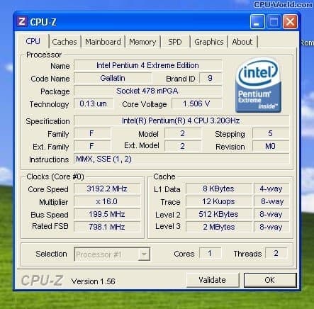
(Intel Pentium 4 Extreme Edition, 2003, is known as the first consumer CPU to include an L3 cache)
In more recent environments, the L3 cache has improved performance by operating as a shared cache in multi-core settings,
but modern systems face bandwidth bottlenecks between the CPU and memory, along with growing demands from graphics and AI workloads that require extremely fast memory access,
making the need for an L4 cache increasingly apparent. An L4 cache can also be shared not only with the CPU but with an integrated GPU (iGPU) as well,
and Intel did in fact introduce an L4 cache in 2013 under the name Crystal Well,
yet as of 2026 the cost remains too high for widespread adoption, so it has not been commercialized to the extent that L3 has and is used primarily in high-performance servers.
Now let's summarize the cache hierarchy.
Cache Hierarchy (Memory Hierarchy)
Level | Capacity | Access Time | Location | Characteristics |
|---|---|---|---|---|
L1 | 32~64KB | 1~4 CPU cycles | Built into CPU core | - Fastest and smallest cache- Separate instruction cache & data cache (L1I, L1D) |
L2 | 256KB~1MB | 10~20 cycles | Near CPU core | - Exists individually per core- Larger than L1 cache but slower |
L3 | 16~64MB | 50~100 cycles | Shared across multiple cores | - Cache shared among multiple cores- Responsible for managing Cache Coherence |
L4 | 64MB~256MB+ | 150~300 cycles | On-package or external chip | - Used in some high-performance servers, AI workloads, and integrated GPUs (iGPU)- Can be shared not only with the CPU but also with the GPU and memory controller |
DRAM | 8GB~1TB+ | 300~500 cycles | Motherboard DIMM slots | - System-wide memory- Larger than L4 cache but slower- Volatile Memory, meaning data is lost when power is removed |
- Level
L1
- Capacity
32~64KB
- Access Time
1~4 CPU cycles
- Location
Built into CPU core
- Characteristics
- Fastest and smallest cache- Separate instruction cache & data cache (L1I, L1D)
- Level
L2
- Capacity
256KB~1MB
- Access Time
10~20 cycles
- Location
Near CPU core
- Characteristics
- Exists individually per core- Larger than L1 cache but slower
- Level
L3
- Capacity
16~64MB
- Access Time
50~100 cycles
- Location
Shared across multiple cores
- Characteristics
- Cache shared among multiple cores- Responsible for managing Cache Coherence
- Level
L4
- Capacity
64MB~256MB+
- Access Time
150~300 cycles
- Location
On-package or external chip
- Characteristics
- Used in some high-performance servers, AI workloads, and integrated GPUs (iGPU)- Can be shared not only with the CPU but also with the GPU and memory controller
- Level
DRAM
- Capacity
8GB~1TB+
- Access Time
300~500 cycles
- Location
Motherboard DIMM slots
- Characteristics
- System-wide memory- Larger than L4 cache but slower- Volatile Memory, meaning data is lost when power is removed
The hierarchy becomes progressively larger but slower as you go from L1 to L4, and when a Cache Miss occurs, the CPU must access DRAM, which significantly degrades CPU performance.
When a Cache Miss occurs and data must be fetched from RAM, this typically takes around 100~300 cycles.
As L4 cache capacity grows larger, it begins to resemble DRAM, and using faster DRAM instead of adding an L4 cache tends to be more cost-effective, which is why L4 cache has not yet seen widespread adoption in consumer PCs.
In particular, with the emergence of HBM (High Bandwidth Memory), which can serve as a replacement for the L4 cache's role, L4 is currently used only in specialized environments such as servers and AI accelerators.
That said, it remains to be seen how things will develop in the future.
(Direct-Mapped Cache image)
How Cache Works
Now let's explain how cache operates.
Cache Line
A cache line is the smallest unit for storing and managing data in cache memory. When the CPU retrieves data from memory, instead of fetching individual bytes or words, it fetches a fixed-size block of data (a cache line) all at once. This improves the efficiency of memory access and optimizes performance by exploiting data locality.
In modern systems, cache lines are typically set to 64 bytes (i.e., 512 bits). Older systems used smaller sizes such as 16 bytes or 32 bytes, but 64 bytes has become the current standard.
A cache line contains not only data but also metadata such as a tag, a Valid Bit, and a Dirty Bit.
Cache Line Structure
A cache line is stored as a single "slot" or "entry" within cache memory, and it contains the following information.
Data
The actual data block fetched from main memory (e.g., 64 bytes).
It includes not only the data the CPU requested but also the surrounding data, exploiting spatial locality.
Tag
Represents the address information of the main memory location that this cache line references.
The tag is used by the cache to identify which memory location the data came from.
Valid Bit
Indicates whether this cache line is filled with valid data (0: empty, 1: valid).
Dirty Bit
Used in write-back caches to indicate that the cache line data has been modified and is not yet synchronized with main memory.
Other Metadata
Temporal information for cache replacement policies (e.g., LRU, Least Recently Used), Cache Coherence state (such as Modified, Exclusive, Shared, and Invalid in the MESI Protocol), and so on.
How Cache Lines Work
Cache lines determine how the CPU retrieves and manages data when accessing memory.
The following is a step-by-step explanation of how this process works.
1. Cache Hit and Cache Miss
When the CPU requests data at memory address X, the cache checks the cache line associated with that address.
Hit: If the requested address already exists in the cache line, the data is returned directly from the cache (fast access).
Miss: If the address is not found in the cache line, the entire cache line, including the requested address and its surrounding data, is fetched from main memory.
2. Data Fetching
When a cache miss occurs, the CPU fetches data in units equal to the cache line size (e.g., 64 bytes) for the address of the requested data.
For example, if data at address 0x1000 is requested, the range 0x1000~0x103F (64 bytes) is fetched all at once.
This exploits spatial locality, based on the assumption that adjacent data is likely to be used soon.
Fetch: refers to the entire operation of bringing data from main memory (RAM) or another cache level into the cache.
Cache fetches are also categorized by situation into Demand Fetch, Prefetch, Speculative Fetch, and others.
3. Cache Line Storage
The fetched cache line is stored in a slot in the cache memory.
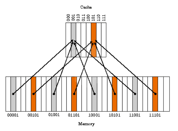
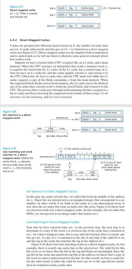
Direct-Mapped Cache: each memory address maps to a fixed cache line position.
Set-Associative Cache: data is stored in one of several cache lines (sets), determined by a replacement policy (such as LRU).
Fully Associative Cache: data can be stored in any position within the cache (rare in practice).
When the cache is full, an existing cache line is evicted (replacement).
4. Write Operations
Write Hit
- Write-Through: updates both the cache and main memory simultaneously.
- Write-Back: updates only the cache and sets the dirty bit, then reflects the change to memory later.
Write Miss
- Write-Allocate: fetches the cache line into the cache, then writes and updates it there.
- No-Write-Allocate: writes directly to main memory without allocating a cache line.
5. Cache Coherence
In a multi-core CPU, the cache line of each core may reference the same memory address.
Data consistency between cache lines is maintained through protocols such as the MESI Protocol (Modified, Exclusive, Shared, Invalid).
Locality
Temporal Locality
- When the same data is accessed repeatedly, the cache hit rate increases.
Spatial Locality
- Efficient when accessing adjacent memory addresses sequentially.
Three Types of Cache Misses
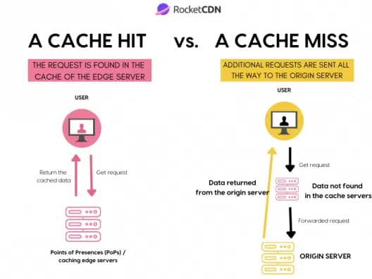
(Image source: https://rocketcdn.me/what-is-a-cache-hit-ratio/)
1. Compulsory Miss
Definition: A cache miss that occurs when data is accessed for the very first time; an unavoidable, inevitable miss.
Also referred to as a "Cold Miss" or "First Reference Miss".
Causes:
Occurs because the data is not present in the cache when the cache is initially empty, or when a program accesses a particular piece of data for the first time
A data fetch is required while the cache line has not yet been populated
Characteristics: These misses occur primarily at the start of program execution; once data has been fetched and loaded into the cache, this type of miss decreases
Example:
When array[0] of int array[100] is read for the first time at program startup, a Compulsory Miss occurs because the data is not yet in the cache.
Subsequent accesses to array[0] are handled as Cache Hits.
How to reduce:
Prefetching: Hardware prefetchers or software-level prefetching can fetch data ahead of time to reduce Compulsory Misses.
While they cannot be eliminated entirely, initial loading speed can be improved.
There are, however, inherent practical limits: since the first access to any data cannot be avoided, these misses are an inevitable consequence of the design.
2. Conflict Miss
Definition: A cache miss that occurs when another piece of data is occupying the same cache line even though there is sufficient space in the cache overall. Also referred to as a "Mapping Miss".
Causes:
When the cache uses direct-mapped or set-associative mapping, multiple memory addresses map to the same cache line, causing conflicts
Characteristics: Independent of cache size; depends on the cache mapping scheme and data access patterns
Example:
When the cache has 4 lines (each 64 bytes) and uses direct-mapped:
Addresses 0x1000 and 0x2000 map to the same cache line (e.g., line 0).
After loading 0x1000, accessing 0x2000 causes 0x1000 to be evicted; accessing 0x1000 again then triggers a Conflict Miss.
How to reduce them:
Use 2-way or 4-way Set-Associative Cache instead of Direct-Mapped Cache to lower the likelihood of conflicts.
Data Padding: adjust the memory layout to avoid conflicts between data that maps to the same cache line.
Memory Alignment: align data structures to cache line boundaries to minimize conflicts.
As a practical limitation, designing a Fully Associative cache eliminates Conflict Misses entirely, but the increased hardware complexity and cost make it impractical.
- When cache associativity is low, data entries overwrite one another, causing misses to occur frequently.
- What is cache associativity? Cache associativity refers to the degree of freedom in how data is mapped to the cache; in other words, it encompasses the Direct-Mapped, Set-Associative, and Fully Associative schemes mentioned above.
3. Capacity Miss
Definition: A cache miss that occurs when processing data larger than the cache size, caused by insufficient cache capacity that forces data to be evicted.
Causes:
When the cache is not large enough to hold all active data (the working set), frequently used data is evicted from the cache and must be fetched again.
Occurrence frequency increases when a program's dataset size exceeds the cache capacity.
Characteristics: Directly dependent on cache size, with little relation to associativity or mapping scheme.
Example:
Repeatedly traversing a 1 MB array on a system with a 256 KB L2 cache:
The first 256 KB is loaded into the cache, but as the traversal approaches the end of the array, excess data overwrites earlier cache lines.
When the traversal loops back to the beginning, the data that was evicted from the cache causes capacity misses.
Ways to reduce:
Increase cache size: Add larger caches such as L2 and L3 to alleviate capacity issues.
Improve data locality: Reduce the working set used by the program, or make memory accesses more local (e.g., block-based processing).
Efficient algorithms: Reduce unnecessary data accesses to lessen the burden on cache capacity.
A practical limitation is that cache size cannot be increased indefinitely, as hardware cost and power consumption become significant concerns.
(Let's try manipulating the cache miss simulator in the playground.)
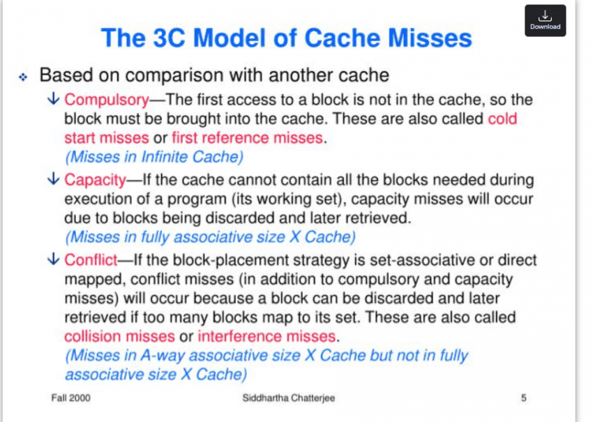
The 3C Model
The three categories of cache misses are commonly referred to as the '3C Model.'
Total cache miss rate = Compulsory + Conflict + Capacity,
Minimizing cache misses as much as possible is, in this sense, a true measure of a programmer's skill.
Examples of How to Reduce 3C Cache Misses
Compulsory Miss: an inevitable miss on first access → mitigated with Prefetching.
Conflict Miss: collision on the same cache line → resolved with Set-Associative Cache (8-way) plus padding.
Capacity Miss: exceeds cache capacity → split the dataset with Blocking.
Writing Cache-Friendly Code
int array[1024][1024]; // 4MB (4 bytes per element)
for (int j = 0; j < 1024; j++)
{ // Row-major access
    for (int i = 0; i < 1024; i++)
    {
        array[i][j] = i + j; // Column-major access (non-contiguous)
    }
}
(Non-cache-friendly code)
int array[1024][1024];
for (int i = 0; i < 1024; i++)
{ // Row-Major Access
    for (int j = 0; j < 1024; j++)
    {
        array[i][j] = i + j; // Row-wise Access (Sequential)
    }
}
(Cache-friendly code)
1. Exploiting Spatial Locality with Sequential Access
In a 2D array in C-family languages, accessing data column by column means the memory addresses are non-contiguous, so cache lines are evicted frequently. For example, array[0][0] and array[1][0] are 4,096 bytes apart (1024 × 4), so the adjacent data loaded into a cache line (64 bytes) goes unused, increasing Capacity Misses.
Accessing data row by row instead means array[i][j] and array[i][j+1] are only 4 bytes apart, allowing you to take full advantage of Spatial Locality.
(Note that this is a matter of how data is laid out in memory: in C-family languages, which store data in row-major order, you should iterate row by row; in languages like MATLAB, which use column-major order, iterating column by column is the correct approach.)
int array[4096][4096]; // 64MB
for (int i = 0; i < 4096; i++)
{
    for (int j = 0; j < 4096; j++)
    {
        array[i][j] *= 2;
    }
}
(Non-cache-friendly code)
int array[4096][4096];
const int BLOCK_SIZE = 64; // Align to cache line (64 bytes) and array size
for (int ii = 0; ii < 4096; ii += BLOCK_SIZE)
{
    for (int jj = 0; jj < 4096; jj += BLOCK_SIZE)
    {
        for (int i = ii; i < ii + BLOCK_SIZE && i < 4096; i++)
        {
            for (int j = jj; j < jj + BLOCK_SIZE && j < 4096; j++)
            {
                array[i][j] *= 2; // Process in 64×64 blocks
            }
        }
    }
}
(Cache-friendly code)
2. Reducing Capacity Misses with Block-Level Processing
Large datasets are processed in chunks sized to fit within the cache, minimizing Capacity Misses.
A 64 MB array exceeds both the L2 (1 MB) and L3 (16 MB) caches, so as traversal progresses toward the end of the array, data loaded early gets evicted and must be fetched again, increasing Capacity Misses.
By splitting the data into 64×64 blocks (16 KB) and processing each block in turn, the likelihood that each block remains in cache is significantly improved.
struct Data
{
    int a; // 4 bytes
    int b; // 4 bytes
} data[1024];

for (int i = 0; i < 1024; i++)
{
    data[i].a = i;           // Likely mapped to the same Cache Line
    data[(i + 256) % 1024].b = i; // High probability of Conflict Miss
}
(Non-cache-friendly struct)
struct Data
{
    int a;          // 4 bytes
    int b;          // 4 bytes
    char padding[56]; // Add padding to align with 64-byte Cache Line
} data[1024];

for (int i = 0; i < 1024; i++)
{
    data[i].a = i;
    data[i].b = i; // Minimize conflicts with sequential access
}
(Cache-friendly struct — do not use in a single-threaded context!)
3. Reducing Conflict Misses with Data Padding
Looking at the original code, data[i] and data[i+256] can be mapped to the same Cache Line. Padding the struct size to 64 bytes ensures that each element maps to its own unique Cache Line.
This also changes the access pattern to be sequential, reinforcing both temporal and spatial locality.
Data Padding is a technique that inserts extra empty space (padding) to improve Memory Alignment and cache performance; it also reduces False Sharing.
3-1. Why Conflicts Occur: A Numerical Breakdown
Environment: direct-mapped, 2 KB cache, 64-byte cache lines
→ Number of sets = 2048 / 64 = 32
Set index calculation:
set_index(addr) = (addr / 64) % 32Because sizeof(Data) = 8, the address offset of data[i] is i × 8.
data[i]       → set = (i × 8 / 64) % 32 = (i / 8) % 32
data[i + 256] → set = ((i + 256) × 8 / 64) % 32
                     = (i/8 + 256×8/64) % 32
                     = (i/8 + 32) % 32
                     = (i/8) % 32       ← Same set as data[i]
Since 32 % 32 = 0, the two addresses always map to the same set.
// When i = 0
data[0].a   → set 0  (loads data[0]..data[7])
data[256].b → set 0  ← same set; in a direct-mapped cache, data[0] is immediately evicted

// When i = 1
data[0].a accessed again → CONFLICT MISS
Note that in a real L1 cache (32 KB, 512 sets), (i/8 + 32) % 512 ≠ (i/8) % 512, so no direct conflict actually occurs there. This example is intended to illustrate why this pattern is dangerous in embedded environments where the cache is small.
The padded version, by contrast, increases sizeof(Data) to 64, so the distance between data[i] and data[i+256] becomes 256 × 64 = 16,384 bytes. In a 32-set cache, (16384/64) % 32 = 256 % 32 = 0, meaning they still map to the same set. In other words, the real benefit of padding is not avoiding set conflicts; it is isolating each element in its own Cache Line to eliminate false sharing. This point is covered in detail in section 3-2 below.
3-2. Scope of the Padding Example: Single-Threaded vs. Multi-Threaded
The padding code shown above can be evaluated in completely opposite ways depending on context.
In single-threaded sequential access, it actually backfires.
With the original struct (no padding, sizeof(Data) = 8), a single Cache Line (64 bytes) holds 8 elements.
1 compulsory miss → followed by 7 consecutive cache hits
Cache line utilization: 8/8 = 100%
Adding 56 bytes of padding (sizeof(Data) = 64) means only 1 element fits in a single Cache Line.
Compulsory miss occurs in every loop iteration
Cache line utilization: 8/64 = 12.5%
→ 87.5% of bandwidth is wasted fetching padding (garbage data)
This effectively destroys spatial locality. For single-threaded sequential access, the version without padding is the right choice. This is why, when writing cache-friendly code, it matters whether the code is single-threaded or not.
When padding becomes the right answer: preventing False Sharing
This technique only delivers benefits in a multi-threaded environment. The problem arises when multiple cores concurrently write to adjacent array elements.
core 0: data[0].a = 1;   // Cache Line A occupied
core 1: data[0].b = 2;   // Same Cache Line A → Invalidate core 0's line
Under the MESI Protocol, when two cores share the same Cache Line and one of them performs a write, the other core's Cache Line transitions to the Invalid state, forcing a re-fetch. In practice, a and b are distinct variables, yet their performance degrades simply because they reside on the same Cache Line. This phenomenon is called False Sharing.
In this situation, padding that isolates each element onto its own Cache Line becomes the solution.
// Proper padding usage in a multi-threaded environment
struct Data {
    int a;
    int b;
    char padding[56]; // Blocking false sharing between cores
} data[1024];

// thread 0: dedicated Cache Line for `data[0]`
// thread 1: dedicated Cache Line for `data[1]` → no mutual invalidation
Summary
Environment | No Padding | With Padding |
|---|---|---|
Single-threaded sequential access | Maximum exploitation of Spatial Locality | Bandwidth waste, counterproductive |
Multi-threaded concurrent writes | False Sharing occurs | Cache Line isolation, the correct approach |
- Environment
Single-threaded sequential access
- No Padding
Maximum exploitation of Spatial Locality
- With Padding
Bandwidth waste, counterproductive
- Environment
Multi-threaded concurrent writes
- No Padding
False Sharing occurs
- With Padding
Cache Line isolation, the correct approach
There are additional examples such as cache blocking and tiling, but given that the post is already quite long and further additions would significantly hurt readability, those topics will be covered in a future post.
Tips for Writing Cache-Friendly Code
Sequential Access: Process arrays row by row to make full use of Cache Lines.
Data Size Tuning: Fit the working dataset within the cache size (L1: 32KB, L2: 256KB, etc.).
Padding: In multi-threaded environments, align data to Cache Line (64-byte) boundaries to prevent False Sharing. Note that padding is counterproductive for single-threaded sequential access.
Prefetching: Use explicit or implicit Prefetching to reduce Compulsory Misses.
Loop Optimization: Design nested loops so that the inner loop accesses contiguous memory.
Beyond these techniques, careful attention to algorithm selection is also important;
take Quicksort and Merge Sort as an example: their average time complexity is identical,
but Quicksort has a cache-friendly access pattern, whereas Merge Sort can be less cache-efficient due to the additional memory space it requires.
This is because Quicksort, when sorting in place, accesses memory sequentially without any additional memory accesses, whereas Merge Sort requires an auxiliary buffer, causing repeated back-and-forth accesses between the buffer and the original array and thereby reducing Cache Line reuse rates.

Make the common case fast.
— David Patterson
Closing Thoughts...
As we have seen, a Cache is not simply "fast memory."
It is a predictive system that governs the flow of data, and it can be understood as the bridge that enables hardware and software to communicate with each other.
That is precisely why we, as programmers, have an obligation to connect hardware and software in a thoughtful and appropriate way.
After all, we are not merely writing code; we are the ones who tell the hardware about our imagination.
References: Randal E. Bryant, David R. O'Hallaron, Computer Systems: A Programmer's Perspective, 3rd Global Edition, Pearson, 2016.